
Why Are My Wire EDM Toolpaths Grayed Out in ESPRIT EDGE?
When getting started with wire EDM programming in ESPRIT EDGE, one of the most common questions is surprisingly simple:
“Why are my EDM toolpaths grayed out?”
You may have a valid solid model displayed in the graphics window, yet when you open the EDM tab, commands such as 2-Axis Contouring, 2-Axis Pocketing, 4-Axis Contouring, and 4-Axis Pocketing remain unavailable.
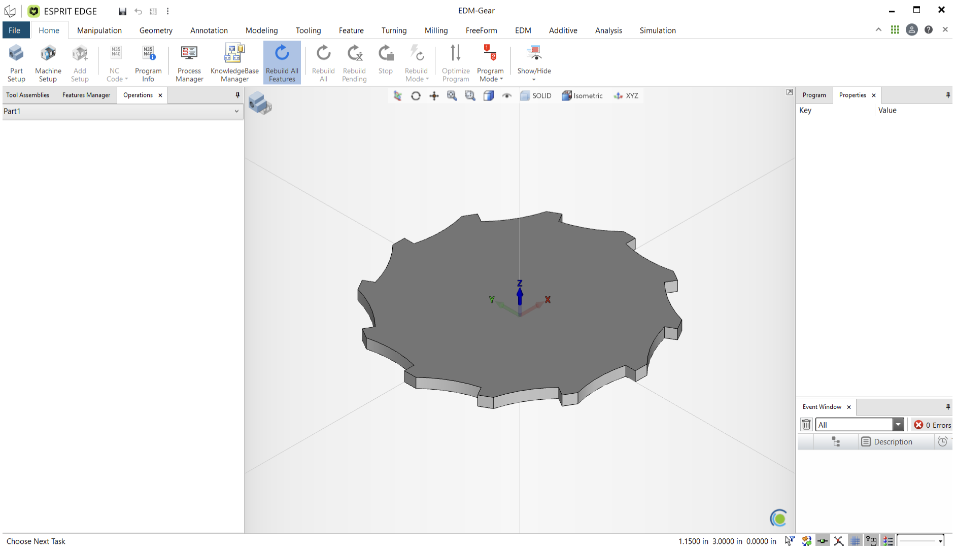
Fortunately, this usually does not indicate a problem with the geometry or the software. The solution is to make sure the project has been properly configured.
There are two essential steps:
- Define the part and stock using Part Setup.
- Define the machine and workpiece using Machine Setup.
Once these items are established, the appropriate EDM programming commands become available.
Understanding Why the EDM Commands Are Unavailable
ESPRIT EDGE needs more than geometry before it can determine which machining functions should be active.
A model may be visible on screen, but the software still needs to understand the role that geometry plays in the manufacturing project. It needs to know what represents the finished part, what represents the stock, and which machine will perform the work.
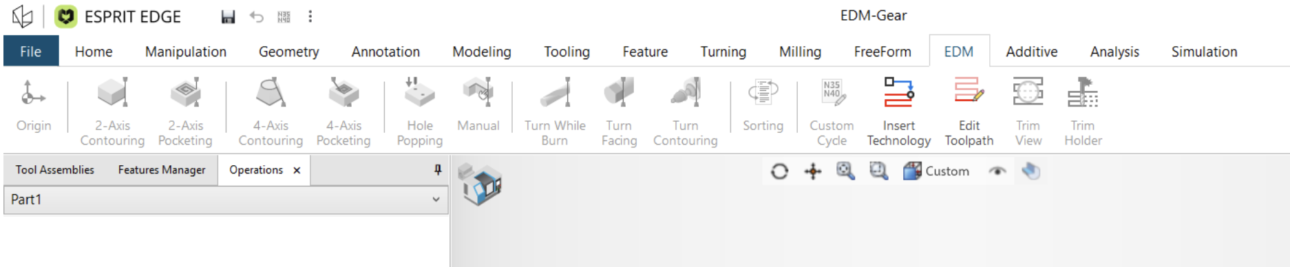
This project definition begins with Part Setup and is completed through Machine Setup.
Step 1: Define the Part
Start from the Home tab and select Part Setup.
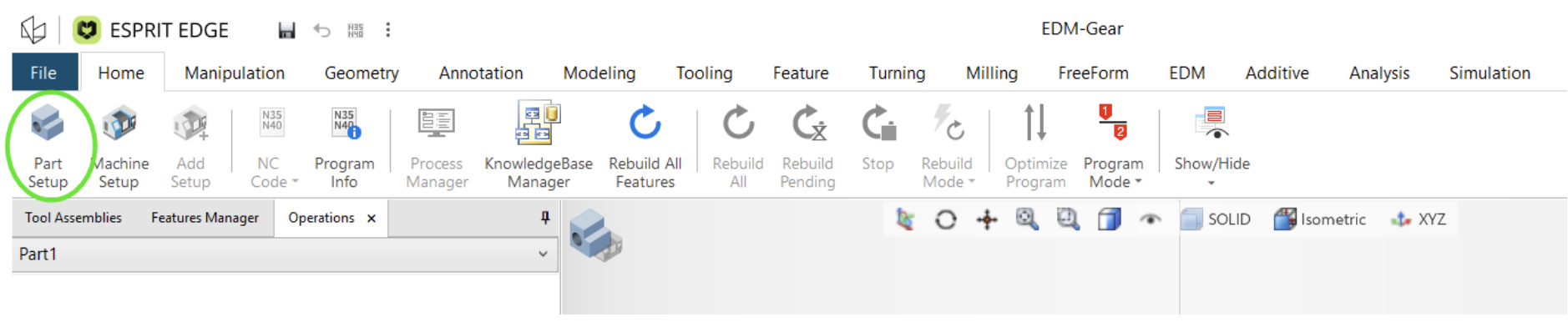
In many workflows, the part will already have been defined during model import. The Import as New Part option can automatically handle this portion of the setup process.
However, there are situations where the part needs to be defined manually. This can occur when creating geometry directly in ESPRIT EDGE or when working with multiple models.
Within Part Setup, select the model under Geometry so ESPRIT EDGE knows which solid represents the finished component. Once the appropriate geometry has been selected, confirm the setup.
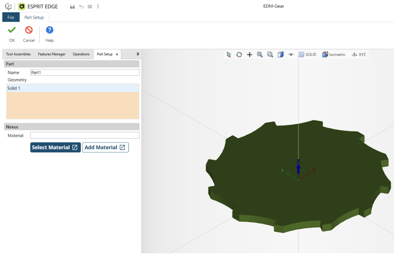
This may appear to be a small step, but it establishes an important relationship between the CAD geometry and the manufacturing project.
Define the Stock
The next step is to identify the material from which the part will be machined.
ESPRIT EDGE provides several options for defining stock, including:
- Rectangular block stock
- Cylindrical bar stock
- Solid-model stock
This flexibility allows the stock definition to match the actual material being used for the job.
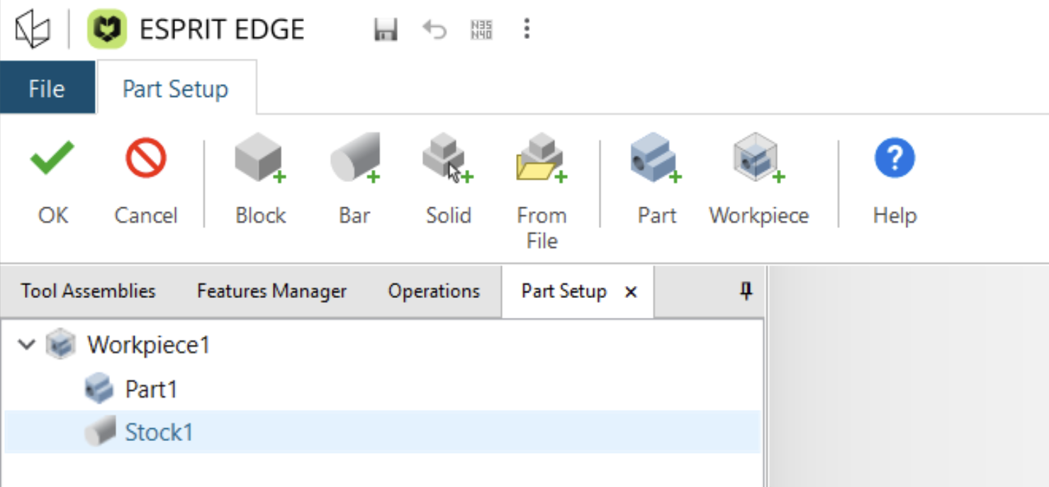
For the example shown here, a cylindrical stock shape is used and offset to the desired nominal size.
Parameters such as the outside diameter and stock length can then be adjusted to represent the starting workpiece.
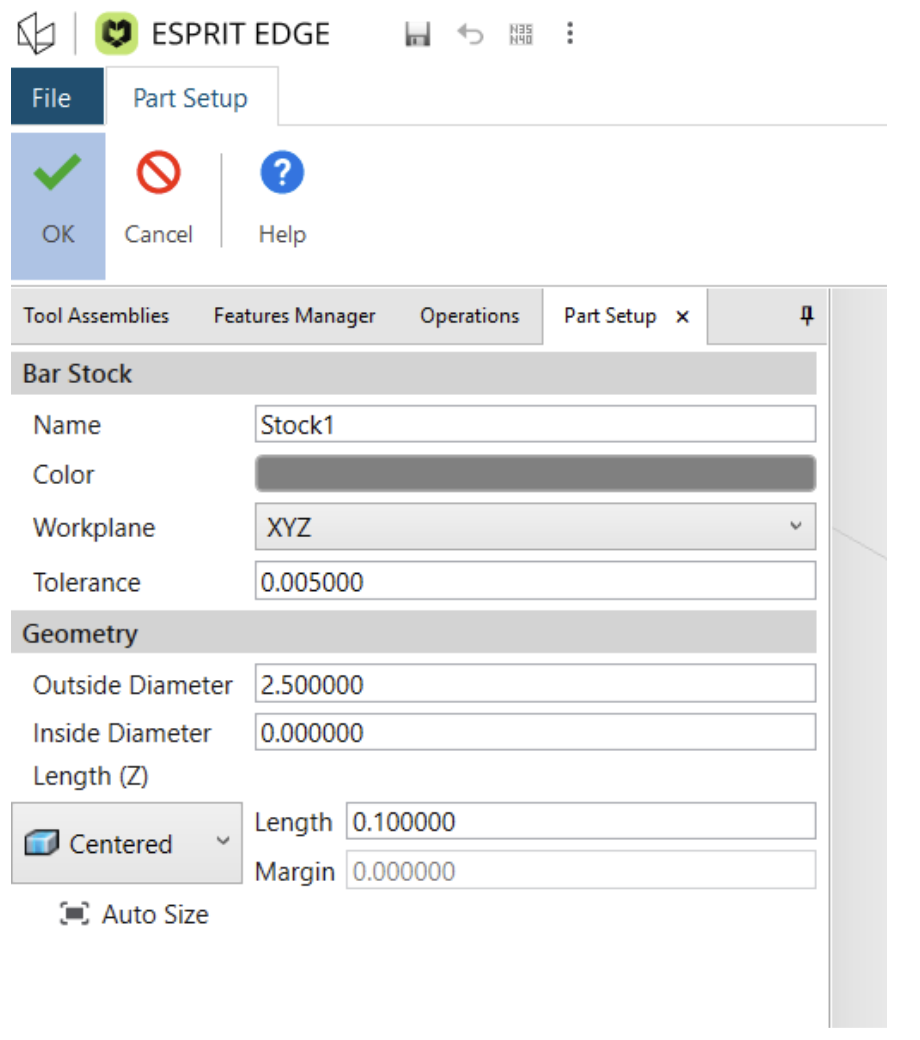
With both the finished part and the raw stock established, the first major stage of the project setup is complete.
Step 2: Configure Machine Setup
After defining the part and stock, move to Machine Setup.
This is the second essential step in preparing the ESPRIT EDGE project.
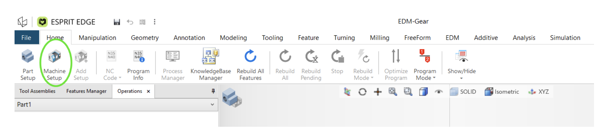
The selected machine is important because ESPRIT EDGE uses the machine definition to activate many of the machine-specific capabilities and settings required for programming.
In this example, a Sodick wire EDM machine is loaded.
Select Machine Setup, browse to the appropriate machine definition, and load it into the project.
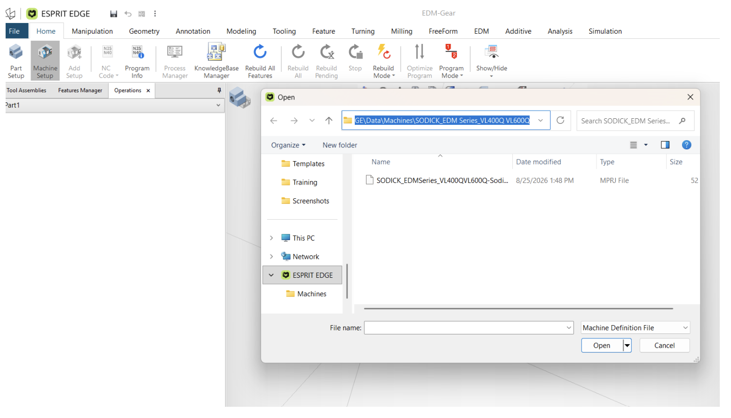
Depending on the machine definition, the initial graphical representation may display more or less detail. For example, you may initially see primarily the machine nozzles rather than a complete machine assembly.
This is perfectly acceptable, and you may move on to the next step.
Add the Workpiece to the Machine
Loading the machine is only part of the Machine Setup process. The workpiece defined earlier must also be associated with the machine.
Once the machine has been loaded, add the workpiece created during Part Setup to the machine configuration.
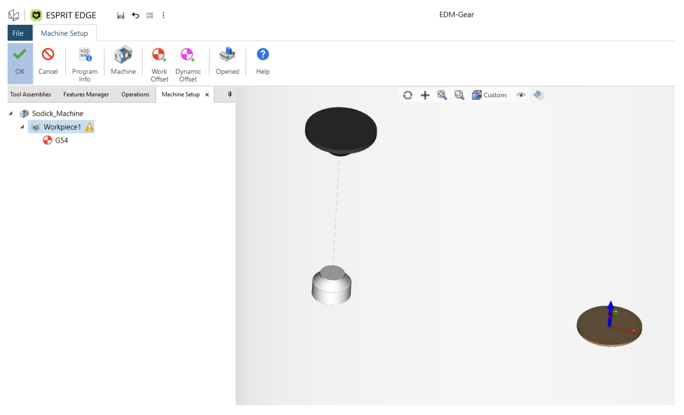
This establishes the connection between three important elements of the project:
Part geometry → Stock → Machine
After confirming the selections, ESPRIT EDGE now has the information it needs to determine which machining functions should be available.
Return to the EDM Tab
With Part Setup and Machine Setup completed, return to the EDM tab.
The previously grayed-out EDM commands should now be active.

At this point, the project is properly configured, and programming can begin.
A Simple Troubleshooting Workflow
When wire EDM toolpaths are unavailable, it is useful to think of the issue as a project setup check rather than immediately assuming something is wrong with the model.
Start by confirming that the model has been designated as the part and that suitable stock has been created. Then verify that the correct EDM machine has been loaded and that the workpiece has been added to the machine configuration.
This simple sequence can resolve what initially appears to be a much more complicated problem.
Why Part and Machine Setup Matter
Part Setup and Machine Setup do more than simply enable commands on the ribbon. Together, they establish the manufacturing context ESPRIT EDGE needs for the project.
The software needs to understand:
What are we machining?
The part geometry answers this question.
What material are we starting with?
The stock definition provides this information.
What equipment will perform the machining?
The machine definition completes the manufacturing environment.
Once these relationships have been established, ESPRIT EDGE can expose the appropriate machine-specific programming functionality.
Final Thoughts
If your wire EDM toolpaths are grayed out in ESPRIT EDGE, the solution may be much simpler than expected.
Before troubleshooting geometry or looking for a software problem, verify these two essential areas:
Part Setup: Define the finished part and the stock.
Machine Setup: Load the appropriate EDM machine and add the workpiece.
Once these steps are complete, return to the EDM tab and confirm that the machining commands are available.
For new ESPRIT EDGE users in particular, understanding this setup sequence is an important foundation. Establishing the part, stock, machine, and workpiece correctly at the beginning of the project helps create a cleaner and more efficient workflow for everything that follows.