An Intro to 5-axis Composite Cycles.
Blending Fillet with the 5th axis
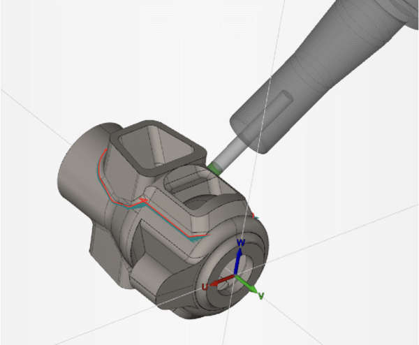
1. Set your Workplane
-
- This time, we want our W- Vector point towards the direction that we want our tool to approach from.
2. Build your Freeform Feature
-
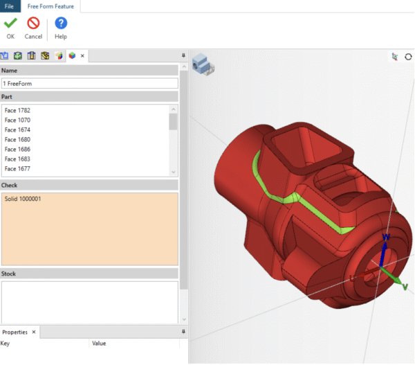
- We want to select our drive surface (Part) along with designating the surface we do not want to touch as “Check”.
- We want to select our drive surface (Part) along with designating the surface we do not want to touch as “Check”.
3. Create your Drive/Projection Surface:
-
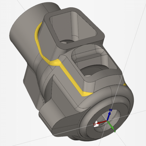
- Here, we want to use 4-borders knitted surface to create our parametric drive surface. This will control the tool path flow as it moves over the part faces following the parametric lines of the drive surface.
4. Create your Composite Cycle: From System Default
a. Tool Path
-
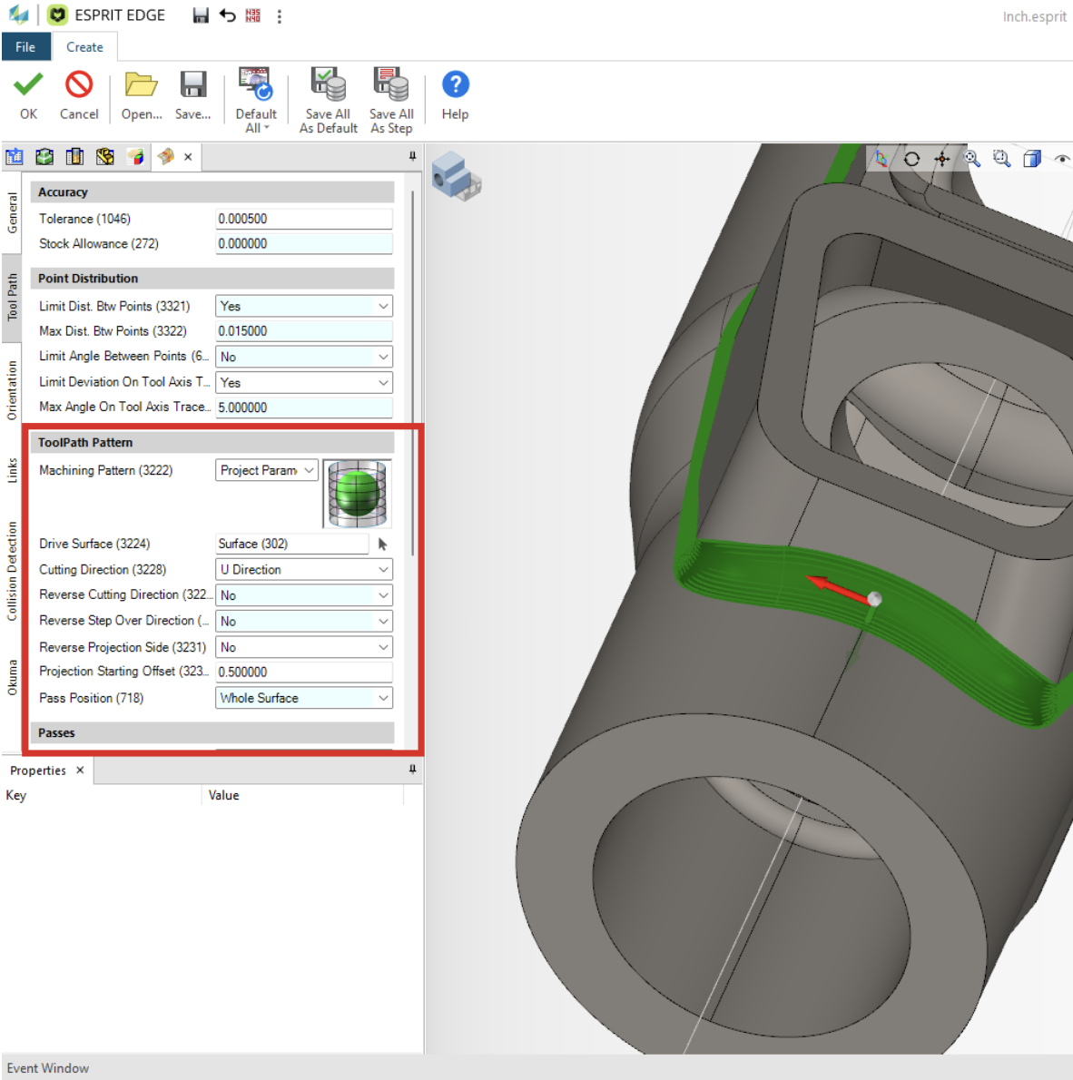
- Machining Pattern- we will use Project Parametric Pattern
- Drive Surface- Select your Knitted Surface. (pay close attention to the surface normal vector)
- IF Needed- Cutting Direction – Verify that your toolpath will flow in the direction of your U/V surface parametric direction
- IF Needed- Reverse Projection Side – If the White surface normal vector is pointing inwards, set this to “Yes”
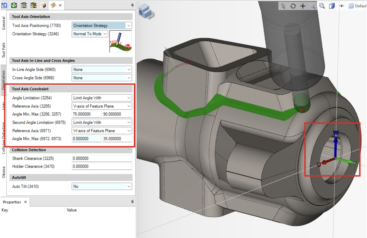
b. Orientation Tab
-
- Angle Limitation – Fixed Angle With
- Reference Axis – Z-Axis
- Fixed Angles – 75°
c. Links Tab
-
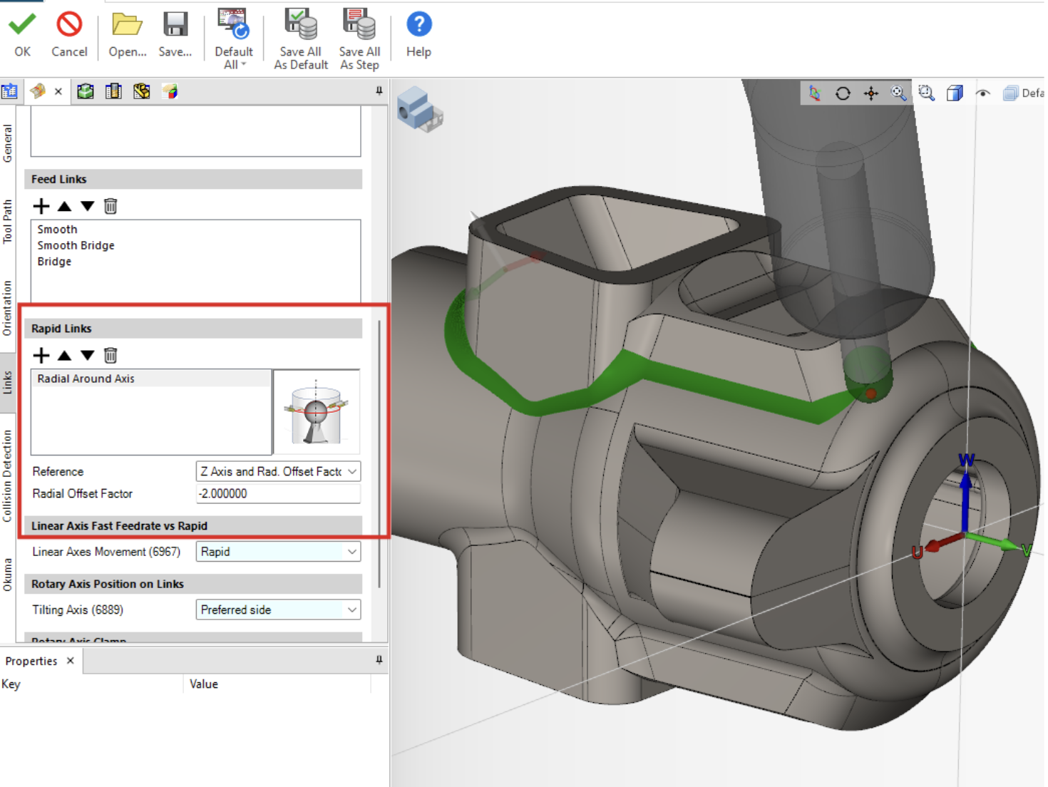
- Rapid Links
- Radial around axis forces the tool to stay perpendicular to the axis we designate.
- Reference- Z Axis radially, utilizing an offset factor
- Radial Offset Factor- This is the clearance factor for tool retraction.
- Tip – this can be set to a negative number to reduce the radial clearance between rapid links in an operation.
- Rapid Links
5. Hit OK
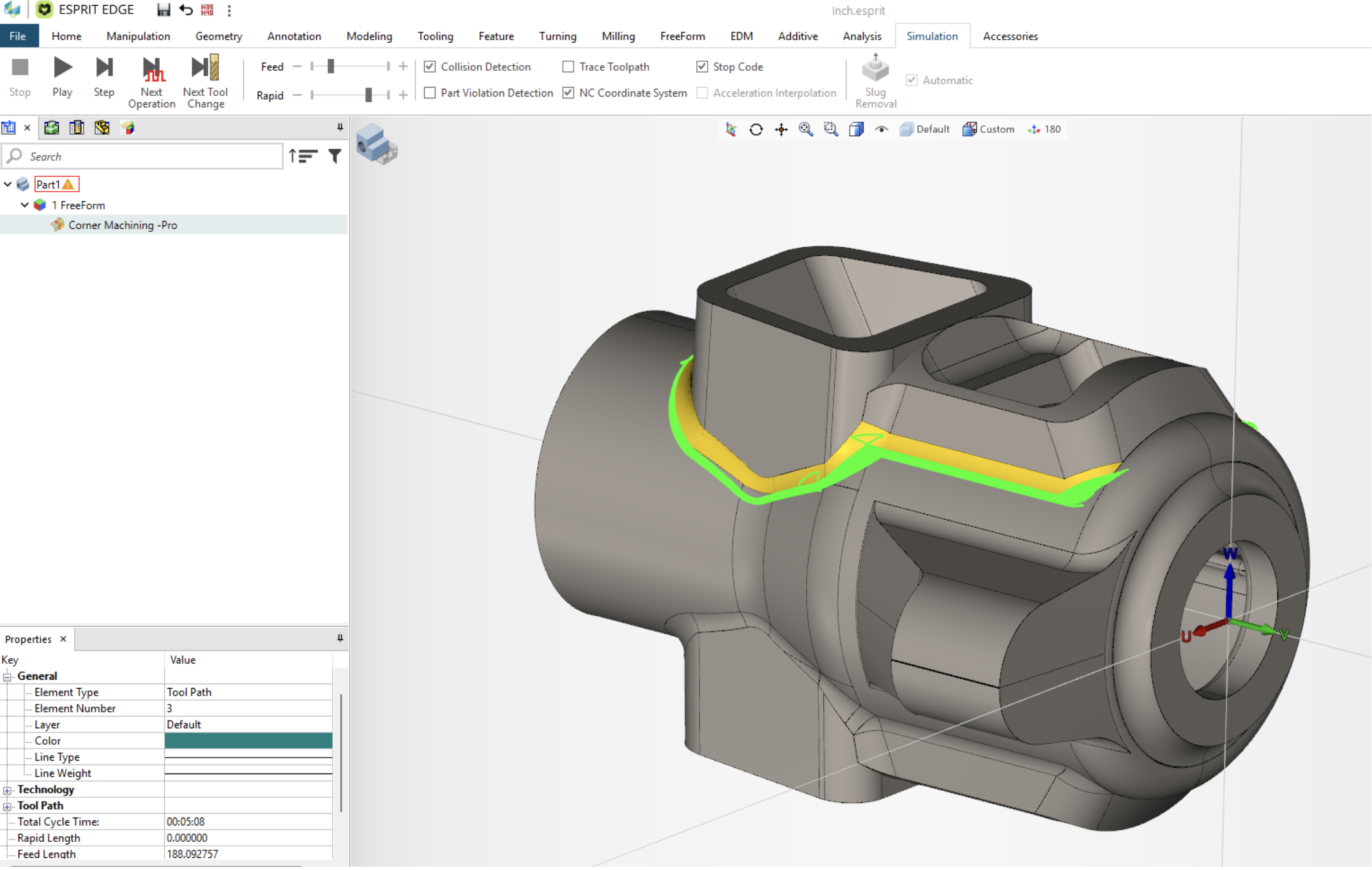
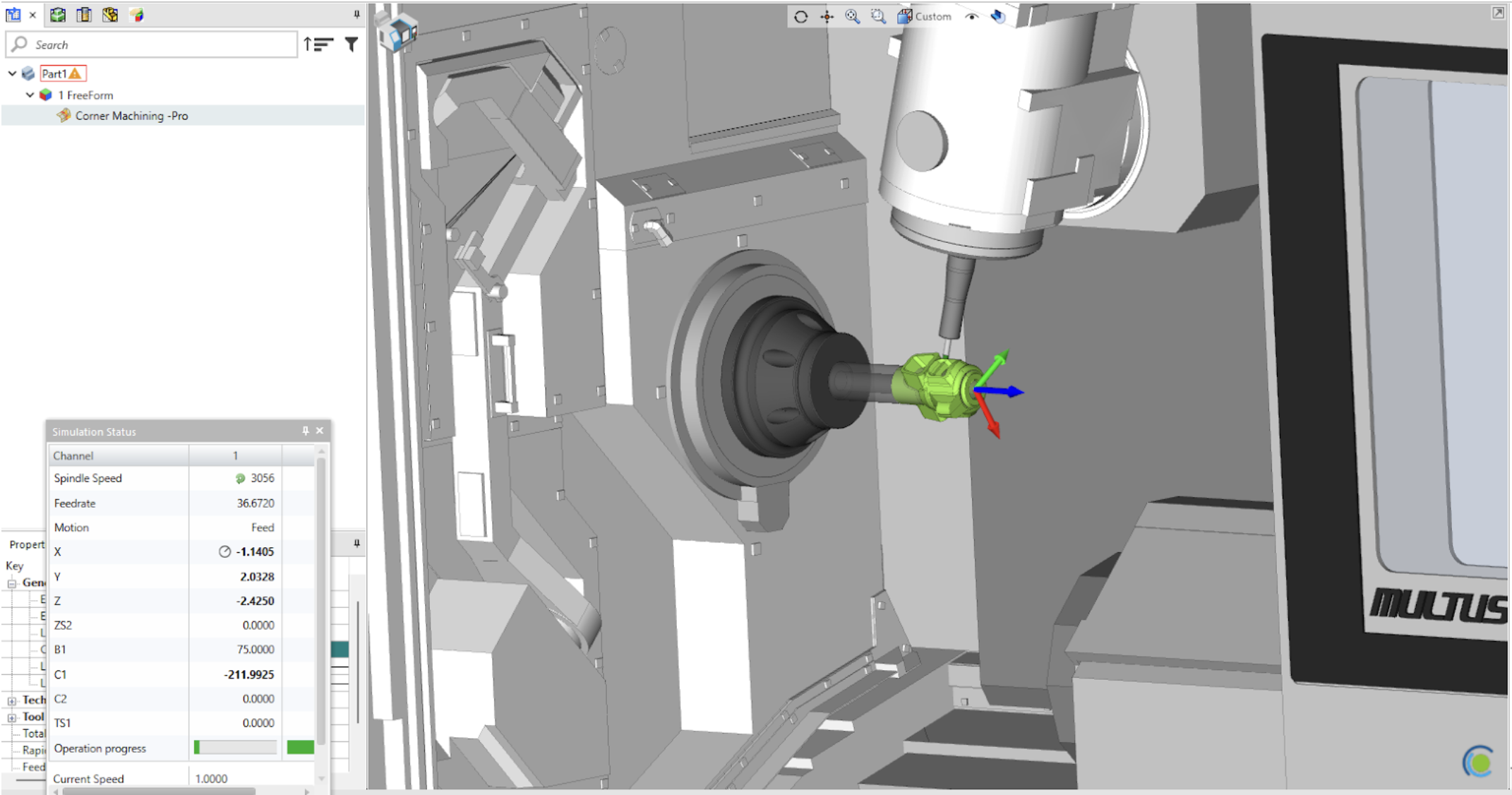
With the simple steps above, creating smooth and controlled toolpath doesn’t have to be a stressful task. If you would like a more detailed demonstration, I would encourage to watch our Youtube tutorial that will walk you through every step of how blend surface fillets using ESPRIT EDGE Composite Cycles.
