Integrating a rotary table fixture into your machining setup can significantly expand your capabilities—especially when working with complex 4-axis or 5-axis parts. With ESPRIT EDGE and Machine Tool Builder, the process of defining, aligning, and testing a rotary table becomes efficient and repeatable.
In this blog, we'll walk through a 3-phase process to create a rotary table fixture model, define its behavior, and validate it within the ESPRIT EDGE environment.
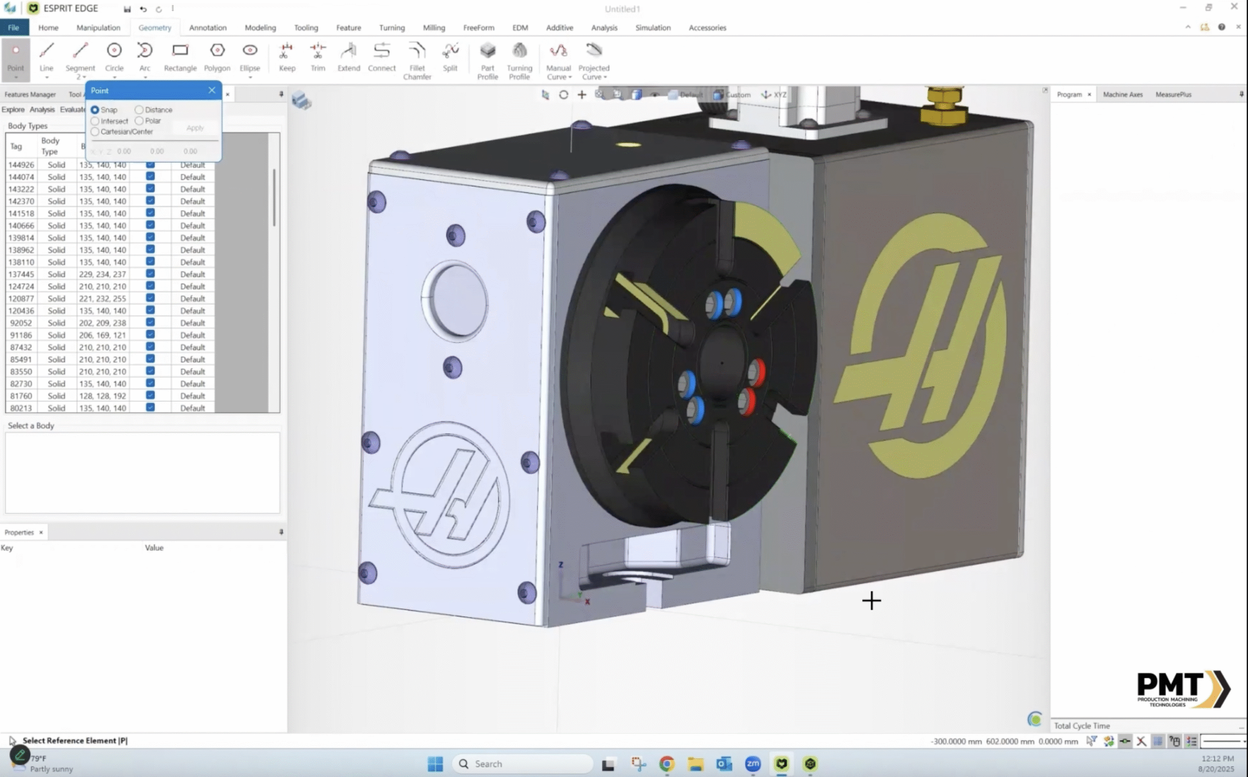
Phase 1: Positioning and Orienting the Solid Model in ESPRIT EDGE
The first step in any successful fixture design is proper alignment. In this phase, we focus on preparing the solid model of the rotary table for integration.
Key Tasks:
- Import the rotary table solid model into ESPRIT EDGE.
- Use the transform tools (Translate and Rotate) to orient the model correctly relative to the machine tool's coordinate system.
- Ensure that the rotary axis (typically the A or B axis) aligns with the expected direction (e.g., along the X, Y, or Z axis).
- Define the mounting surface so it is located at the origin. This location will later be used to attach the table to the machine tool.
- Save the Oriented solids as a Fixture GDML file by selecting all solids and going to File > Save As.
Pro Tips:
- Always align the center of rotation with the origin or known fixture offset to simplify downstream setup.
- Use simple geometry to ensure alignment accuracy.

Phase 2: Defining Rotational Axis and Attachment Points in Machine Tool Builder
Once the model is correctly positioned, it’s time to define the behavior and integration of the rotary table using Machine Tool Builder.
Key Tasks:
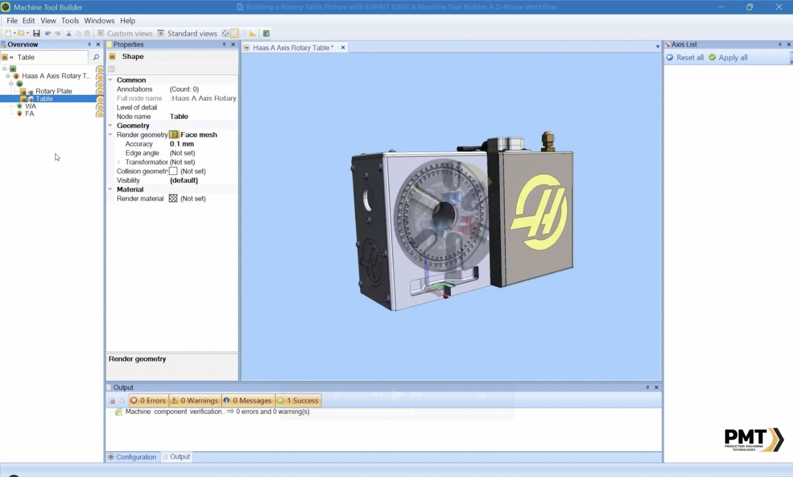
- Open the Machine Tool Builder and open the Fixture GDML file you created for the rotary table.
- Simplify Solids:
- Find the parts of the table that will be rotating, and rename them to find them more easily.
- Remove any unnecessary solids that may cause collisions with the moving solids.
- Select all stationary solids for the table and perform a right-click > Combine to merge them all into a single solid (this will reduce the file size greatly.)
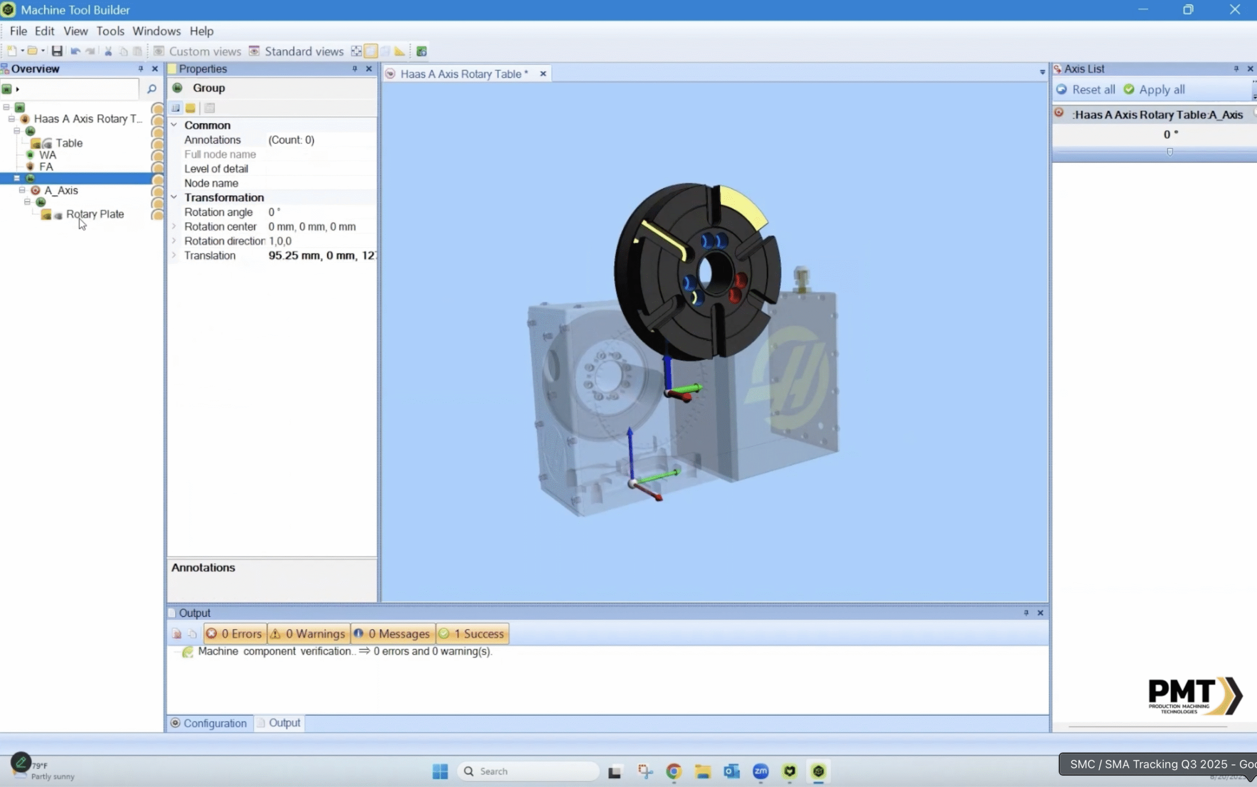
- Assign the rotational axis:
- Define the axis vector (direction of rotation) by right-clicking the main node of the tree and selecting Add Item > Group, then adding a rotation axis and setting its Axis Direction.
- Add the pivot point and attachment location by changing the translation of the rotation axis parent node (the group node created earlier) by the distance between the table mounting point and the center of the front face of the rotary table.
- Label the axis (e.g., "A Axis") and confirm its kinematic relationship to the base machine.
- Set the Attachment points and moving solids:
- Drag and drop the attachment points into the group node that was translated.
- Add a new group node under the Rotational Axis node, and move the rotating solids to this new node. (You may need to subtract the translations entered in the other group node from this group node so the solids placed inside are not affected by that translation.)
- Disable axis limits, home positions, and set other kinematic constraints as necessary, and save the changes to your GDML file.
Pro Tips:
- Use visual tools in Machine Tool Builder to verify rotational behavior.
- Validate that the rotation does not interfere with surrounding machine components or workpiece geometry.

Phase 3: Loading and Testing the Fixture in ESPRIT EDGE
With the rotary table defined and mounted, return to ESPRIT EDGE to test the setup in a simulated environment.
Key Tasks:
- Load the rotary table fixture into a machine setup in ESPRIT EDGE.
- Simulate the axis movements using the Machine Axes tool in ESPRIT EDGE.
- Observe the rotary motion, direction, and attachment points of the fixture to the table and workpiece to the fixture.
- Adjust mounting location using the ESPRIT EDGE translation tools if necessary.
Key Validation Checks:
- Does the rotary axis behave as defined in Phase 2?
- Are the mounting points accurate during simulation?
- Does the fixture allow access to all critical machining features?
Pro Tips:
- Save different fixture configurations for easy swapping between jobs.
- Use ESPRIT's collision detection tools to verify safe operation before running a real part.

Final Thoughts
Integrating a rotary table fixture into ESPRIT EDGE using Machine Tool Builder isn’t just about modeling—it’s about building a trustworthy digital twin before chips fly. By breaking the process into three structured phases—positioning, defining, and validating—you ensure that your setup is robust, repeatable, and production-ready.
Whether you’re prototyping or running full production, this workflow gives you the flexibility and confidence to tackle more complex geometries with ease.
