Cutter compensation is one of the most critical—and occasionally misunderstood—features in CNC programming. In ESPRIT Edge, understanding how offset values influence both simulation and machine behavior is essential for accurate toolpath validation and production-ready G-code.
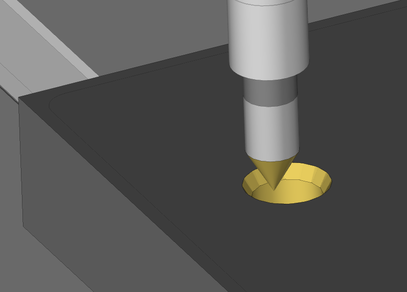
This post focuses on a specific issue many users encounter: a simulation where the tool appears to drill directly into the center of a hole instead of cutting a chamfered profile. We’ll explain why that happens and how the Offset Register Value impacts the simulation results.

The Simulation Issue
In the example demonstrated, a chamfering tool is used to machine a countersunk hole. The tool path:
- Plunges near center
- Feeds outward to profile the chamfer
- Returns to center to retract
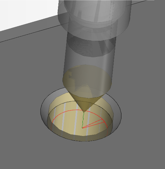
However, in the simulation, the tool appears to simply drill straight down, ignoring the intended chamfering motion.
This confusing visual behavior leads many programmers to question whether the toolpath is incorrect—when in fact, it’s the simulation logic responding to a parameter most users overlook.
Cutter Compensation Parameters in ESPRIT Edge
To understand the issue, let’s walk through the five core cutter comp parameters in ESPRIT:
1. Offset Side Computer
- Defines which side of the toolpath the cutter should follow.
- Typically set to Right for climb milling.
2. Offset Tool Radius
- Enables or disables automatic tool radius compensation.
- Set to Yes when you want the software to handle radius adjustments.
- Set to No for centerline-following paths (e.g., engraving or probing).
3. Cutter Comp NC
- Sets the G-code instruction: G41 (Left), G42 (Right), or Off (no comp).
- When G41/G42 is used, two additional fields become available:
4. Offset Register NC
- Specifies the D-word register (e.g., D01, D02) associated with the tool compensation value on the control.
5. Offset Register Value
Used for simulation only, this value mimics how the control interprets cutter compensation.


Why the Simulation Looks Incorrect
In the example, the Offset Tool Radius is already enabled, so ESPRIT offsets the tool correctly. However, the Offset Register Value is set to 0.1875”, which is half the tool diameter.
This creates a double compensation effect:
- The software offsets the path once using the tool radius.
- The simulation then adds another offset of 0.1875", as if the machine control were applying a D-register value of the same amount.
Result: The effective profile collapses into a central point, which looks like the tool is drilling vertically rather than cutting a chamfer.
How to Fix It
To correct the simulation:
- Set the Offset Register Value to 0 if the tool radius is already being handled by the software.
- Use a small nonzero value only if simulating additional tool wear compensation or spring passes.
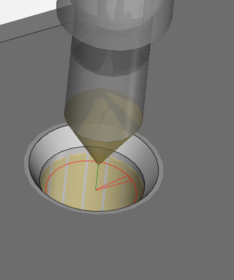
This ensures the simulation matches your programming intent and eliminates misleading toolpath visuals.
Visual Reference
Here’s a look at the simulated issue and the correction:
| Incorrect Simulation (with Offset Register Value) | Correct Simulation (Offset Register = 0) |
| Tool appears to drill straight down | Tool follows the expected chamfer path |
Positive and Negative Wear Offsets
Here’s a look at the intended use of this parameter:
| Small Positive Offset Register Value | Small NegativeOffset Register Value |
| Tool leaves extra material on profile | Tool takes extra material from profile |
Final Thoughts
Understanding how the Offset Register Value affects simulation behavior is crucial when fine-tuning toolpaths in ESPRIT Edge. This setting allows for nuanced visualization of secondary offsets—useful for tool wear scenarios—but it should be used carefully to avoid misrepresenting the actual machining process.
Whether you’re debugging an unexpected simulation result or teaching CAM best practices, this insight can save hours of confusion.
